
Presto MRC-16 Lathe Motor
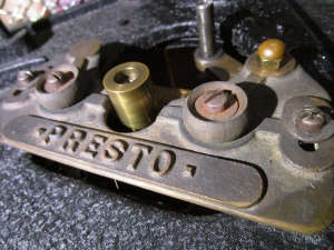
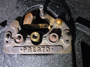
Presto disk recording lathes are often still in active use nowadays, nearly 80 years after they originally left the factory in New York. Let us have a closer look at what keeps them spinning!
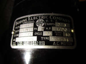
A sturdy Synchronous AC motor, of course! In this instance, it is a 1/20 HP, 4 pole unit, manufactured by Bodine Electric Company in Chicago, IL, around 1940. This is fitted on a Presto MRC-16 lathe, seen here with the platter and drive idler removed.
This motor was designed to spin at 1800 rpm when powered by 60 Hz AC (mains power frequency in the USA). Synchronous AC motors can only spin at a speed defined by the number of poles and the mains frequency. Voltage does not affect their speed, although each motor is designed for a particular line voltage (in this case 110 VAC, to match domestic power plugs in the USA in 1930).
To use such a motor in Europe (230 VAC, 50 Hz domestic power), the first thing we need is a step-down transformer or a frequency converter.
A step-down transformer does not change the frequency, so the motor would run at 50 Hz, causing it to spin at 1500 rpm. Not only will the platter spin too slow, but the motor would also run too hot! A 50 Hz motor would need to be a bit bigger, for the same power rating. To compensate, the voltage would need to be a bit lower than 110 VAC. In addition, new rubber rollers will need to be made, to different dimensions, to give the correct ratio to spin the platter at the correct speed. A separate roller is required for each speed, 33 1/3, 45, 78 rpm, or any other speed of interest.
We can supply such step-down transformers and rubber rollers, or machined capstan/motor shaft sleeves, for most idler-drive, friction-drive, rim-drive, or belt-drive lathes and turntables, to convert from 60 Hz to 50 Hz operation or the other way around.
A frequency converter is the more elegant solution, which we recommend for all professional disk recording and mastering installations.
However, not just any inverter, UPS, industrial VFD or frequency converter can be used for disk recording lathes! These old motors need a fairly clean sine wave at the desired frequency. Any other input will at best make them noisy, or at worst, overheat them. In addition, since speed depends on the frequency, any instability in frequency will cause speed instability (drift or wow & flutter).
A proper frequency converter is rather expensive and there is really only one reliable solution: The Agnew Analog Reference Instruments Type 191. It offers a clean 50 Hz or 60 Hz sine wave, can be powered by any voltage/frequency of your choice and we even make a version powered by DC for mobile use (broadcasting trucks, vans, RV's, caravans, boats, etc) or off-grid locations and renewable energy installations. The frequency is quartz-locked and super-stable, offering a significant improvement over mains power in most locations.
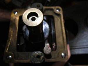
Upon figuring out how to correctly supply your motor with power, there's just one more thing: Maintenance! These motors were well- made and will last a very long time, if properly cared for. What they need is regular lubrication! Did you notice this fitting with spring cap next to the motor shaft?
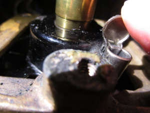
That's right, open it! Now, apply a few drops of Agnew Analog Reference Instruments Type 1201 oil (this is good for Presto, Rek-O-Kut and Fairchild lathes, see our Lubricants section for other types) and wait a few minutes for it to work its way to the bearing.
That was the top bearing.
Time for the bottom one! Yes, there's one of these lubricators at the bottom as well. Good luck getting to it...!
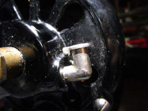
Lubricate the motor weekly and our telephone will ring a bit less frequently!
Time to get running!
These motors are quiet and vibrations are quite low. At 60 Hz the temperature should remain around 40°C/104°F.
At 50 Hz with our Type 1760 transformer, the temperature remained at 45°C/113°F after an hour of use.
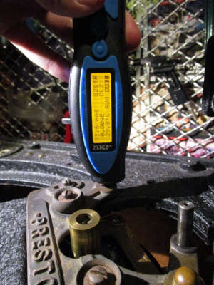
So what is this clicking noise when the motor starts and stops?
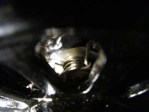
See this spring mechanism in there? A single click at start and stop comes from there and is perfectly normal. This is a centrifugal switch, disengaging the motor starting circuit components once the rotor has reached a certain speed. The operating principles of this switch are described in detail by its inventor, Clifford F. Thompson, assignor to Bodine Electric Company, in his US Patent 1,897,405, titled "Speed Responsive Electric Switch". His application was filed on May 20, 1931 and the patent was granted on February 14, 1933, offering a chronological bearing on the technology discussed herein.
It is always impressive to experience how well these old machines still function, using rather primitive but very effective means, which have proven capable of outliving their inventors and manufacturers.
