Restoring a 1954 Hardinge HLV Super Precision Toolroom Lathe: The Carriage
Finding a Hardinge HLV can be challenging enough, especially if, like us, you happen to be located in Europe. At 1400 lbs, shipping and handling gets complicated. In a previous post, we described the joys of forklifting the beast onto a platform trolley (with suitable structural support added to the building), to get it to the workshop, though narrow corridors and doorways. Once there, it had to be lifted off the trolley and placed directly on the floor. With no chance of being able to drive the period-correct forklift truck into the shop, we had to get creative. A hydraulic engine hoist along with slings and tacks got the job done neatly. With the lathe on the floor and properly leveled, it was time to check it over, replacing, adjusting, lubricating and cleaning parts along the way!
All fine with the handwheel assembly, just cleaned it, adjusted and lubricated it. The issue was still there when turning the second gear in the train by hand. Time to start pulling off the tailstock, power feed control box, cross-slides, levers, leadscrew, carriage, etc, to be able to eventually remove the apron and open it up.
While on the subject of rectifiers... These huge stacks sure do look interesting, but they are selenium rectifiers. This is bad news! Selenium does not age well. They develop a rising resistance over time, which burns up power as heat. Eventually, they will burn out and when they do, they will release selenium vapor, which is extremely toxic. At least it stinks horribly, so you will realize fast enough and run away screaming while flailing your arms in the air. It is very easy to replace them, long before this happens, with a silicon rectifier bridge or even a few vacuum tube rectifiers if you want to be really intense about it. Back to the carriage...
With the apron open, I could confirm that the pinion engaging the rack is pinned to its shaft, as expected. But I was expecting to find the taper pin missing, which would easily explain the slipping pinion! Instead, an oversize pin was tightly fitted, interfering with the bearing! Oh, dear! The pinion gear, however, was indeed slipping! At this point I stopped and had a good look at all the parts lists, manuals, and relevant literature for hints.
A pinned gear can only possibly slip under two circumstances: Either the pin must be missing, or it must be broken into three parts!
Since the pin was not missing, it was either broken into three parts, or there's some other kind of fitting there that I haven't figured out (another clutch?). A steel taper pin of that size breaking in three, with no stripped gear teeth or other major damage, seemed so utterly unlikely, that I actually spent an hour just looking at the assembly in case there was something more elaborate hiding somewhere. Eventually, when I was convinced that it couldn't possibly be anything else, I removed the pin....
... in three pieces!!! When an engineer encounters something like that, they just have to figure out how this could have possibly have happened. A closer look revealed the cause:
This wasn't a taper pin at all! It was just a piece of rolled up steel shim stock, forced into the hole! No wonder this machine ended up being offered for sale! At least this thing broke easily when someone tried to do something stupid, preventing serious damage to more expensive parts.
With the apron disassembled, it is a good occasion to replace all the bearings, especially since the pinion shaft bearing was damaged by the shim pin protruding from the hole and the entire apron was on the disgusting side of filthy. Upon further dismantling, one of the needle roller bearings was found to be missing a few rollers and another was of the wrong type. Whoever was there before me shouldn't have been there.
Scraping off the muck and remains of the silicone sealant previously used to seal the apron against oil leaks (not very successfully as it was leaking like a sieve) was the most boring part of the job. I turned a new steel taper pin to the correct length to not interfere with the bearing (using a Lorch lathe I restored a while back), pressed out all old bearings and pressed in new ones of the correct type, adjusted everything, including the clasp-nut (not really a half-nut, there are two halves there) mechanism, made sure the interlock plate is back in place and the interlock actually works and got everything ready for reassembly. Popular opinion dictates that RTV silicone shall be used as gasket and while it would work well and I have used it a lot in automotive restoration work, I decided against it. There is no significant pressure build-up within the apron and it would be nice to be able to open it up again if need be, without worrying about scraping off RTV gasket remains. Instead, I cut out a simple paper gasket, which has proven perfectly adequate sealing the apron.
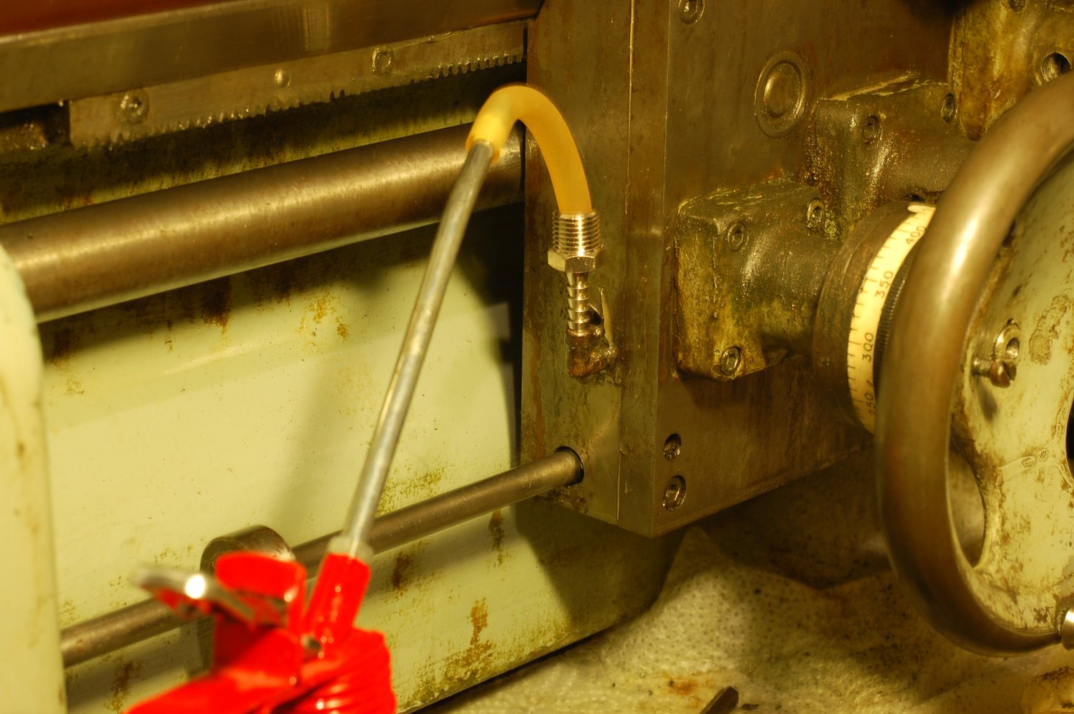
Testing the fit, taking apart again, installing gasket, screwing the two apron halves together, installing on carriage, putting the carriage back on the bed, fitting levers, cranks, handwheel and power feed motor and filling up with oil. It is just me or is this oil filler a size or two smaller than it ought to be?
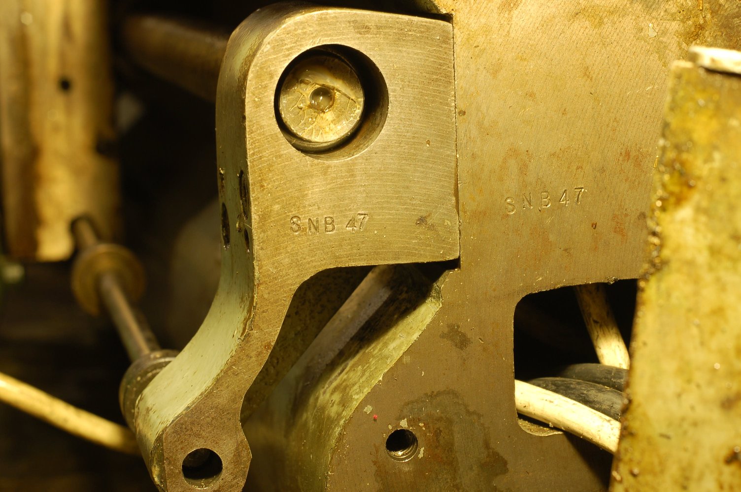
A most useful feature on the HLV is the positive pressure lubrication system fitted to the carriage. This ensures the ways are easily and adequately lubricated.
There is a sight glass on the side, a plug on the back and a properly dimensioned filler on top. The manual calls for the same slideway oil I have been using on all other machine tools in the shop, which is very convenient.
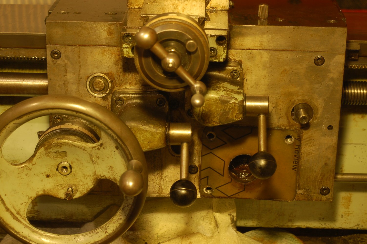
The gibs were all adjusted as the final step and the entire carriage now runs like new. Time to move on to other parts of the machine!
Stay tuned!